EMU Resource Extraction – Digging Up Freedom
SLPA is built on a simple principle: if you can store heat and move gas, you can move anything. The propulsion architecture is only half the story. The other half is how we obtain working gas and bulk mass off-world without rockets, refineries, or megastructures.
This page describes the gas-driven EMU (Extraction Mass Uplift) launcher – an in-situ mass launch system that turns subsurface ice and frozen volatiles into a reusable “barrel” for launching material into orbit using solar-heated gas.
1. Overview: Turning the Ground into a Launcher
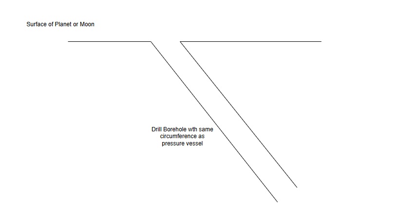
Instead of building a physical gun barrel out of metal, the SLPA architecture uses the terrain itself as the structure. A robotic miner drills into ice or volatile-rich ground, freezes a solid column, and then drills a narrow acceleration EMU through that column.
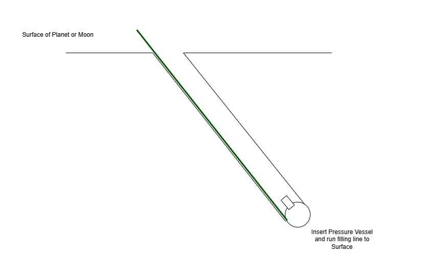
Underneath this frozen barrel, a compact pressure chamber houses the engineered hardware: a pressure vessel, fast-acting valve, and instrumentation. Pressurised gas from a surface gas plant is fed down to this chamber and released into the EMU to accelerate projectiles into space.
The result is a gas cannon formed from the landscape itself – a reusable, self-healing launcher with almost no imported structure.
EMU Launcher – Recommended Launch Angle Ranges
| Angle Range | Meaning | When Used |
|---|---|---|
| 0°–20° | Very shallow | Low-gravity worlds; efficient horizontal orbit injection |
| 20°–30° | Gentle slope | General-purpose EMU launches with balanced vertical and horizontal velocity |
| 30°–45° | Standard range | Most EMU launchers on the Moon and similar bodies; good all-round performance |
| 45°–60° | Steep | High orbits; higher-gravity surfaces; polar or steep ballistic trajectories |
| 60°–90° | Very steep / vertical | Special cases: escape trajectories or depots directly overhead; niche use |
EMU Ice Barrel Requirements Across Different Worlds (5–10 kg Projectile)
| World | Surface Gravity | Required Exit Velocity | Typical Barrel Length | Peak Pressure Needed | Notes |
|---|---|---|---|---|---|
| Moon | 1.62 m/s² (0.165 g) | ~2.4 km/s | 35–60 m | 80–120 bar | Ideal EMU environment. Frozen regolith adds wall strength. |
| Ceres | 0.27 m/s² | ~0.6 km/s | 10–20 m | 25–40 bar | Extremely low difficulty. Near-perfect for mass drivers. |
| Europa | 1.31 m/s² | ~2.0 km/s | 30–50 m | 70–100 bar | Ice quality excellent; stable barrel formation at depth. |
| Ganymede | 1.43 m/s² | ~2.0–2.1 km/s | 35–55 m | 80–120 bar | Similar to Europa; regolith overburden gives strong support. |
| Enceladus | 0.11 m/s² | ~0.2–0.3 km/s | 5–10 m | 5–15 bar | Tiny escape velocity. EMUs here are extremely efficient. |
| Titan | 1.35 m/s² | ~2.6 km/s | 50–90 m | 120–180 bar | Dense atmosphere → EMU works only for surface-to-upper-atmosphere mass lift. |
| Mars | 3.71 m/s² (0.38 g) | ~3.6–4.0 km/s | 120–200 m | 200–300 bar | Not suitable for pure ice barrels; hybrid reinforced barrels required. |
EMU Throughput Scaling (5–10 kg Payload, 24-Hour Delivery)
Even with conservative assumptions—payloads of 5–10 kg per shell and firing intervals of 15, 30, or 60 minutes—throughput accelerates rapidly with tube count. The table below shows total payload mass delivered to orbit in a 24-hour period. A 50-tube installation firing every 15 minutes lifts 24–48 tonnes per day into lunar orbit. At 100 tubes, throughput reaches 48–96 tonnes per day, demonstrating how EMUs transition from experimental systems to full industrial mass-lift infrastructure. With even modest clustering, the EMU system expands rapidly in throughput. A 50-tube array firing every 15 minutes lifts 24–48 tonnes per day into lunar orbit, demonstrating why EMUs become a decisive enabler for large-scale off-world construction.
| Firing Interval | Tubes | 5 kg Payload (t/day) |
10 kg Payload (t/day) |
|---|---|---|---|
| 15 min | 1 | 0.48 | 0.96 |
| 10 | 4.8 | 9.6 | |
| 50 | 24 | 48 | |
| 100 | 48 | 96 | |
| 30 min | 1 | 0.24 | 0.48 |
| 10 | 2.4 | 4.8 | |
| 50 | 12 | 24 | |
| 100 | 24 | 48 | |
| 60 min | 1 | 0.12 | 0.24 |
| 10 | 1.2 | 2.4 | |
| 50 | 6 | 12 | |
| 100 | 12 | 24 |
2. Building the In-Situ Barrel
2.1 Drilling the Primary Shaft
- A shaft is drilled Launch Angle (10–90°) into subsurface ice or ice-regolith.
- The shaft diameter is large enough to:
- install a compact pressure chamber at the bottom, and
- leave sufficient frozen material to act as a strong barrel wall.
Drill Primary Shaft
2.2 Creating the Bottom Pressure Chamber
- a robust pressure vessel,
- a fast-acting gas valve,
- pressure and temperature sensors.
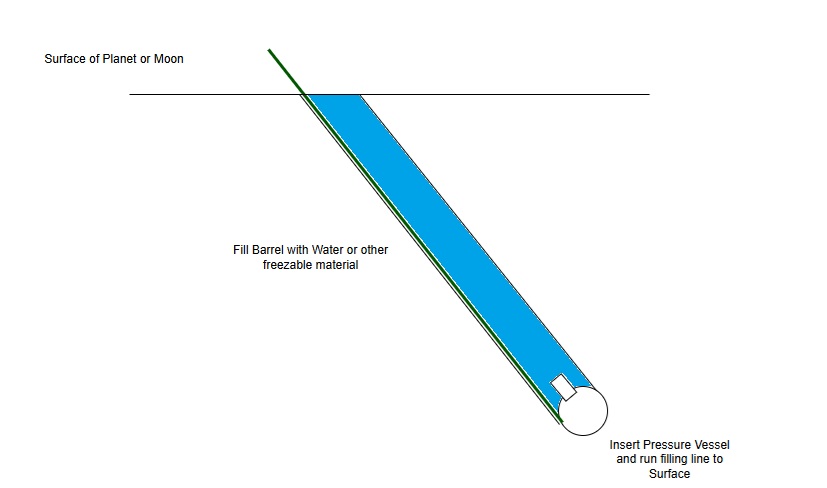
2.3 Filling and Freezing the Barrel Column
- the natural cold of the environment, and
- radiative cooling to space.
- This frozen column becomes the structural body of the barrel.
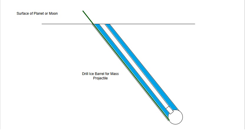
2.4 Drilling the Acceleration Bore
- A narrow, straight EMU is drilled through the frozen column from the pressure chamber to the surface.
- This acceleration EMU is the actual “gun tube”.
- The frozen column around it acts as a thick barrel wall, confined by the surrounding terrain.
3. Launch Cycle: Gas Cannon in a Single Tube
Once the barrel is formed, a typical launch sequence is:
- Load projectile – a slug of ice, a regolith puck, or a sealed payload pod is positioned at the base of the acceleration bore.
- Charge the pressure vessel – the surface gas plant generates pressurised hot gas (steam, CO₂, mixed gas) and feeds it down the gas line into the buried pressure chamber.
- Valve opening – the fast-acting valve between the pressure chamber and the EMU opens, allowing gas to expand into the bore.
- Acceleration – the projectile is accelerated up the EMU by the expanding gas and exits at high velocity towards orbit.
- Recovery period – local heating and partial melting around the EMU are allowed to refreeze, stabilising the barrel for the next shot.
4. Why the Single-Tube Design is Structurally Robust
4.1 Monolithic Load Path
- The frozen column and surrounding ground form a single, continuous load path.
- Pressure loads from the gas are carried through the engineered pressure vessel and along the narrow EMU into the frozen walls.
4.2 Reduced Blowout Risk
- The high-pressure region is limited to the engineered pressure vessel and a short coupling section.
- The frozen barrel only sees pressure along a narrow bore, not across a large cavity.
- The terrain provides natural hoop confinement.
4.3 Controllable Pressure Curve
- Gas generation is decoupled from launch – pressure can be built slowly and safely.
- The valve timing defines the pressure-time curve.
- Allows tuning of acceleration, peak stresses, and thermal load.
5. Self-Healing, and Reuse
- The barrel refreezes after each launch, restoring structure.
- The EMU can be re-melted and re-drilled if degradation occurs.
- The pressure module is replaceable and upgradable.
6. Shell Selection: Iron-Based Projectiles
EMU launcher projectiles are implemented as iron shells filled with compacted lunar regolith. Lunar mare soils contain metallic iron grains and iron-bearing minerals that can be magnetically separated and melted using solar or resistive furnaces. This provides a scalable, fully in-situ metal supply for projectile casings.
Rationale
- Gas seal: A smooth, cylindrical iron shell provides a reliable seal against the bore for efficient pressure transfer.
- Mechanical strength: Iron handles accelerations on the order of 10³–10⁴ g without fracture when given a thick base and squat geometry.
- Low abrasion: The metal shell and optional obturator ring protect the throat liner from direct contact with raw regolith.
- Predictable ballistics: Standardised mass and geometry simplify trajectory tuning and orbital capture.
Shell Construction
-
Iron shell body
Short, thick-based cylinder cast from locally produced iron, with a smooth outer surface matched to the bore diameter. -
Compacted or sintered regolith core
Regolith is pressed (and optionally sintered or glassified) inside the shell to provide the bulk of the mass. -
Optional obturation ring
A slightly softer iron or ceramic ring at the base improves sealing and takes most of the sliding wear. The ring can be replaced as part of routine launcher maintenance.
In-Orbit Utility
Once captured in orbit, iron shells are treated as standard logistics units rather than expendable hardware:
- Structural stock: Empty shells can be welded or bolted into trusses, racks, counterweights, and radiation shielding walls.
- Reusable containers: After unloading regolith, shells can be refilled with refined metals, powders, or other cargoes.
- Manufacturing feedstock: Shells can be cut, rolled, or remelted as input material for orbital fabrication.
- Returnable units (optional): Where transport capacity allows, emptied shells can be returned to the surface, refilled, and relaunched, forming a closed logistics loop.
Extension to Other Bodies
The same iron-shell architecture can be applied at other low-gravity bodies (e.g. Ceres, icy moons) using locally produced metal casings. Where convenient, outbound miners can collect shells staged in orbit on the way to their destination, or deposit shells in staging orbits for later reuse.
7. Barrel Mouth, Sublimation Control, and Maintenance
The EMU launcher uses a deep, ice-supported bore as a natural pressure vessel. At depth, ice and ice-rich regolith remain stable for geological timescales due to low temperatures and shielding from direct vacuum. Sublimation becomes significant only in the final section near the surface, where the barrel opens to space and is exposed to solar heating.
Deep Barrel Stability
- Subsurface ice: At depths of several metres and below, ice is cold and confined by overburden, so sublimation rates are negligible.
- Structural role: Ice-rich regolith behaves as a cryogenic concrete, providing stable walls for the main acceleration section.
- Thermal environment: The deep bore operates in a narrow temperature band, limiting thermal cycling and mechanical fatigue.
Surface Throat and Liner
Only the last ~0.5–1.0 m near the surface requires special treatment to control sublimation and erosion. This region is implemented as a hard, non-volatile throat:
- Hard liner: A short liner of sintered regolith, cast basalt glass, ceramic, or metal is installed at the top of the ice barrel.
- Sacrificial section: The upper ~50 cm is treated as a sacrificial segment that can be replaced periodically as it erodes or roughens.
- Smooth bore: The liner interior is finished smooth to reduce gas leakage, turbulence, and mechanical wear on the obturation ring.
Surface Cover and Sun Shield
To further suppress sublimation and protect the throat, the launcher mouth is covered when not firing:
- Protective cover: A simple hatch or sliding cover closes over the bore between launches, blocking direct line-of-sight to space.
- Sun shield: A fixed baffle or hood provides permanent shadow over the launcher mouth, limiting thermal input from the Sun.
- Thermal control: Optional reflective coatings or multilayer insulation around the throat reduce heating of the upper regolith.
Inspection and Maintenance
- Routine inspection: The throat liner and cover mechanisms are inspected on a fixed schedule (e.g. after a defined number of shots).
- Liner replacement: The sacrificial upper liner section is designed as a modular insert that can be swapped out with minimal tooling.
- Profile control: Bore geometry and surface roughness are monitored; deviations are corrected by replacing or resurfacing liner modules.
By combining a deep, ice-supported barrel with a short, replaceable hard liner and a simple surface cover, the EMU launcher maintains long-term structural stability while minimising sublimation and erosion effects at the surface interface.
8. Integration with SLPA Logistics
The EMU launcher feeds SLPA’s orbital depots:
- Water for crew, thermal cores, and steam propulsion.
- CO₂ and volatiles for STIP thrusters and mixed-gas modes.
- Regolith and structural mass for orbital construction.
It requires only local materials and sunlight.
9. Why This Rounds Out the Architecture
This system closes SLPA’s logistics loop:
- Thermal cores store solar heat.
- STIP thrusters convert heat to thrust.
- Depots store gas and thermal energy.
- Borehole launchers supply depots from planetary surfaces.
10. Scalability and Multi-Bore Operations
- Multiple small bores are safer and more redundant than one large bore.
- Example: ten 5 kg-class bores outperform a single 50 kg EMU in reliability and throughput.
- Bores can be tuned to gas type: steam, CO₂, mixed gases.
- Incremental growth: add bores as mining capability expands.
11. Angular Flexibility and Site Versatility
The EMU launcher is not limited to vertical shafts or flat terrain. Its geometry can be adapted to the environment and mission profile.
11.1 Installation on Flat or Raised Terrain
- Works on flat ice sheets, crater walls, ridges, or sloped terrain.
- Robots can choose sites with optimal ice thickness, stability, or sunlight conditions.
- No need for long flat runways or precision-fabricated structures.
11.2 Adjustable Shaft Angles
- Shafts may be vertical, angled 10–30°, or oriented toward specific orbital targets.
- Angled launch reduces required gas pressure and gravity losses.
- Eastward-angled bores on Mars can exploit rotational velocity for extra delta-v.
11.3 Barrel Longevity Through Angle Selection
- Shallow angles reduce peak stress on frozen walls.
- Vertical bores simplify drilling but require higher gas pressure.
- Mid-angled bores provide the best balance for repeated shots.
11.4 Multi-Bore Launch Fans
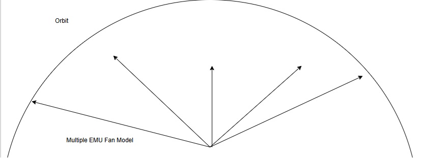
- Several bores with different angles allow delivery to multiple orbital depots.
- Forms a “launch fan” for redundancy and multi-direction launches.
- Continuous operation even if one EMU requires refreezing or maintenance.